- Introduction
- Maintenance
- Preparation
- Service specifications
- Diagnostics
- 2JZ-GE Engine
- 2JZ-GTE Engine
- 2JZ-GTE Turbocharging
- 2JZ-GE Emission control
- 2JZ-GTE Emission control
- 2JZ-GE SFI
- 2JZ-GTE SFI
- Cooling
- Lubrication
- Ignition system 2JZ-GE
- Ignition system 2JZ-GTE
- Starting system
- Charging system
- Clutch
- W58 manual transmission
- V160 manual transmission
- A340E 2JZ-GE automatic transmission
- A340E 2JZ-GTE automatic transmission
- Propeller shaft
- Suspension and axle
- Brake system
- Steering
- Supplemental restraint system
- Body electrical system
- Body
- Air conditioning system
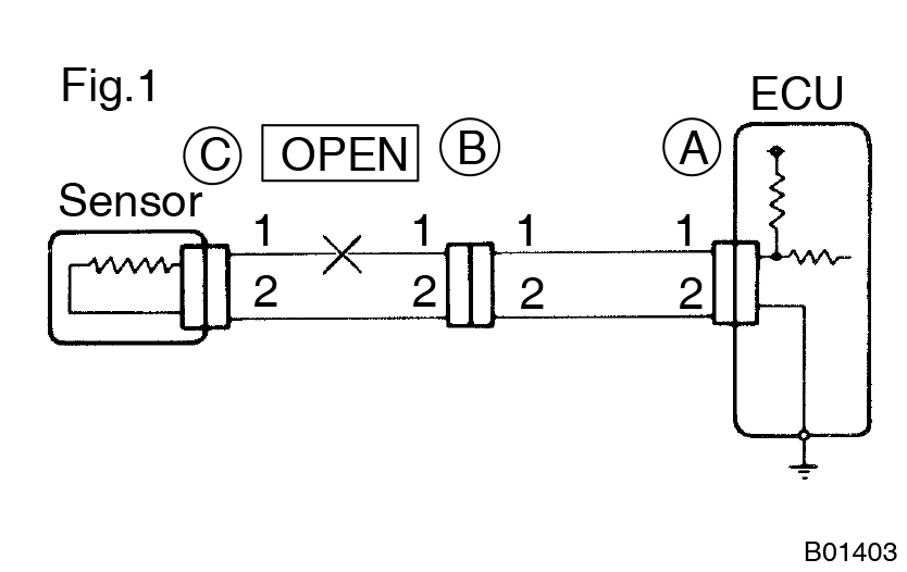
For the open circuit in the wire harness in Fig. 1, perform ”(a) Continuity Check” or ”(b) Voltage Check” to locate the section.

- Check the continuity.
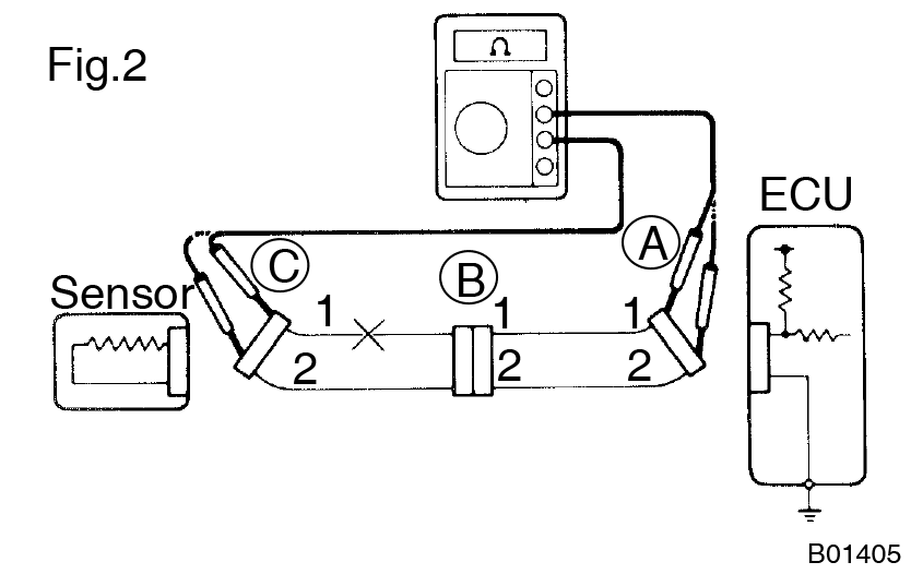
- Disconnect connectors (A) and (C) and measure the resistance between them.
In the case of Fig. 2,
Between terminal 1 of connector (A) and terminal 1 of connector (C) → No continuity (open)
Between terminal 2 of connector (A) and terminal 2 of connector (C) → Continuity
Therefore, it is found out that there is an open circuit between terminal 1 of connector (A) and terminal 1 of connector (C).
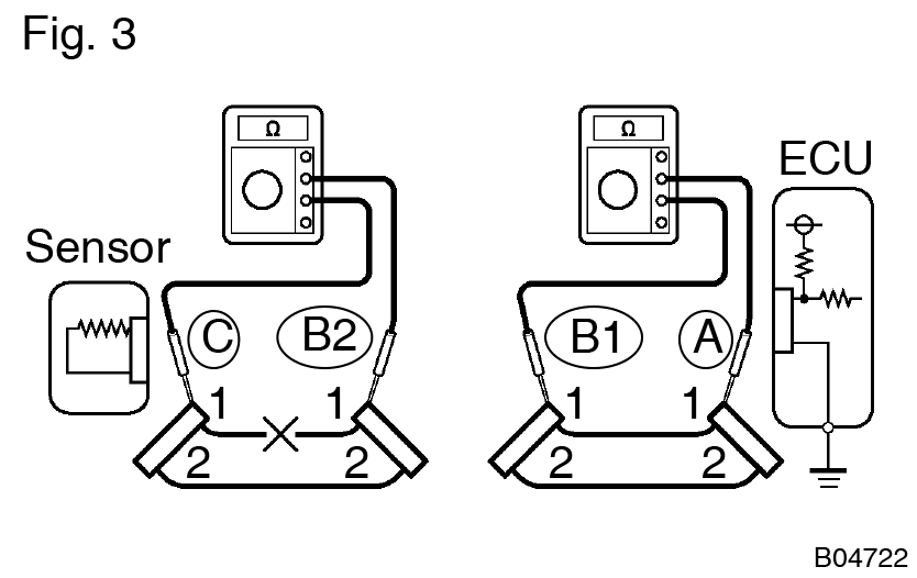
- Disconnect connector ”B” and measure the resistance between the connectors.
In the case of Fig.3,
Between terminal 1 of connector ”A” and terminal 1 of connector ”B1” → Continuity
Between terminal 1 of connector ”B2” and terminal 1 of connector ”C” → No continuity (open)
Therefore, it is found out that there is an open circuit between terminal 1 of connector ”B2” and terminal 1 of connector ”C”.

- Disconnect connectors (A) and (C) and measure the resistance between them.
- Check the voltage.
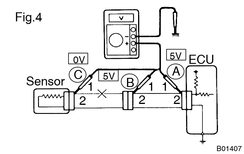
In a circuit in which voltage is applied (to the ECU connector terminal), an open circuit can be checked for by conducting a voltage check.- As shown in Fig. 4, with each connector still connected, measure the voltage between body ground and terminal 1 of connector (A) at the ECU 5V output terminal, terminal 1 of connector (B), and terminal 1 of connector (C), in that order.
If the results are:
5 V: Between Terminal 1 of connector (A) and Body Ground
5 V: Between Terminal 1 of connector (B) and Body Ground
0 V: Between Terminal 1 of connector (C) and Body Ground
then it is found out that there is an open circuit in the wire harness between terminal 1 of (B) and terminal 1 of (C).
- As shown in Fig. 4, with each connector still connected, measure the voltage between body ground and terminal 1 of connector (A) at the ECU 5V output terminal, terminal 1 of connector (B), and terminal 1 of connector (C), in that order.


